Ray Marching
Introduction
I had previously implemented a ray tracer for a university course. I did not know what Ray Marching method was, to be honest. I found out that it was a very useful method in some cases like playing with fog and clouds or abstract shapes with signed distance functions. So I have to learn that. It will help me get better writing shaders with shadertoy.
Ray Marching Algorithm
So, the ray marching algorithm has some similarities with ray tracing. We send some rays to the screen just like we are doing ray tracing. However, this time, we move along the ray in certain amounts in steps instead of directly checking for intersections between rays and the objects. In each step, we first determine what is the closest distance to one of the objects in the scene and advance along the ray with that distance.
This way, at the end of each step, we guarantee that we do not pass through an object. When the minimum distance becomes so small that it is negligible, we stop the ray marching and return the t value to use it for determining the intersection point. The algorithm is visually shown below:
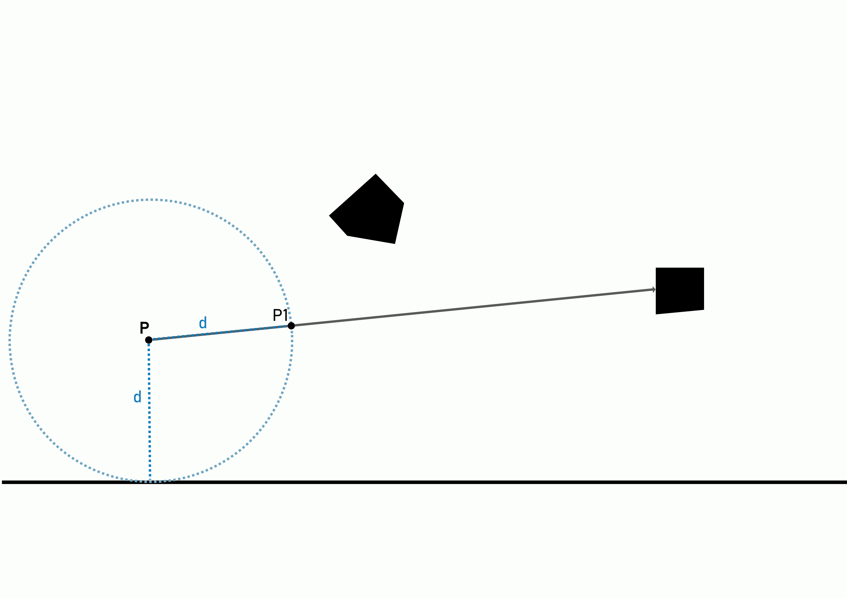
Ray Marching Algorithm
Sending Rays and Camera System
We have to build a camera system and use it for casting rays to the scene. For this, we first have to get the appropriate pixel coordinates. In shadertoy, we do it as follows:
void mainImage( out vec4 fragColor, in vec2 fragCoord )
{
    vec2 uv = (fragCoord - 0.5*iResolution.xy)/iResolution.y;

    ...
}
This helps us get the uv coordinates without any stretching.
Secondly, I also wanted to define a struct for the Camera as follows:
struct Camera
{
    vec3 Position;
    float Zoom;
}
Normally, I have to include the target as well but I want to implement a simple camera that orbits around the origin and I have a plan for that. I'm going to explain that too.
In mainImage function, I add a camera object like this:
void mainImage( out vec4 fragColor, in vec2 fragCoord )
{
    vec2 uv = (fragCoord - 0.5*iResolution.xy)/iResolution.y;

    Camera cam;
    cam.Position = vec3(0.0, 1.0, 10.0);
    cam.Zoom     = 1.0;
}
Now, we have to get the ray direction for the fragment we are rendering. We use our camera and the fragment coordinates that we have derived(uv coordinates). For this we define a function called getRayDirection.
vec3 getRayDirection(in vec2 pixelCoordinates, in Camera camera)
{
    vec3 forward = vec3(0.0, 0.0, -1.0);

    vec3 right   = normalize(cross(vec3(0.0,1.0,0.0), -forward));
    vec3 up      = cross(-forward, right);

    vec3 centerCoordinates = camera.Position + forward*camera.Zoom;
    vec3 intersection      = centerCoordinates + pixelCoordinates.x*right + pixelCoordinates.y*up;
    vec3 rayDirection      = normalize(intersection - cameraPosition);

    return rayDirection;
}
So, what happens in the function above? We first define a coordinate system for the camera. This is a right-handed coordinate system just like in OpenGL. When we use our right hand and make our thumb point right, index finger point upwards and the middle finger towards us, we get a right-handed coordinate system. The thumb becomes x, the index finger becomes y and the middle finger becomes the z-axis. This coordinate system is shown below:
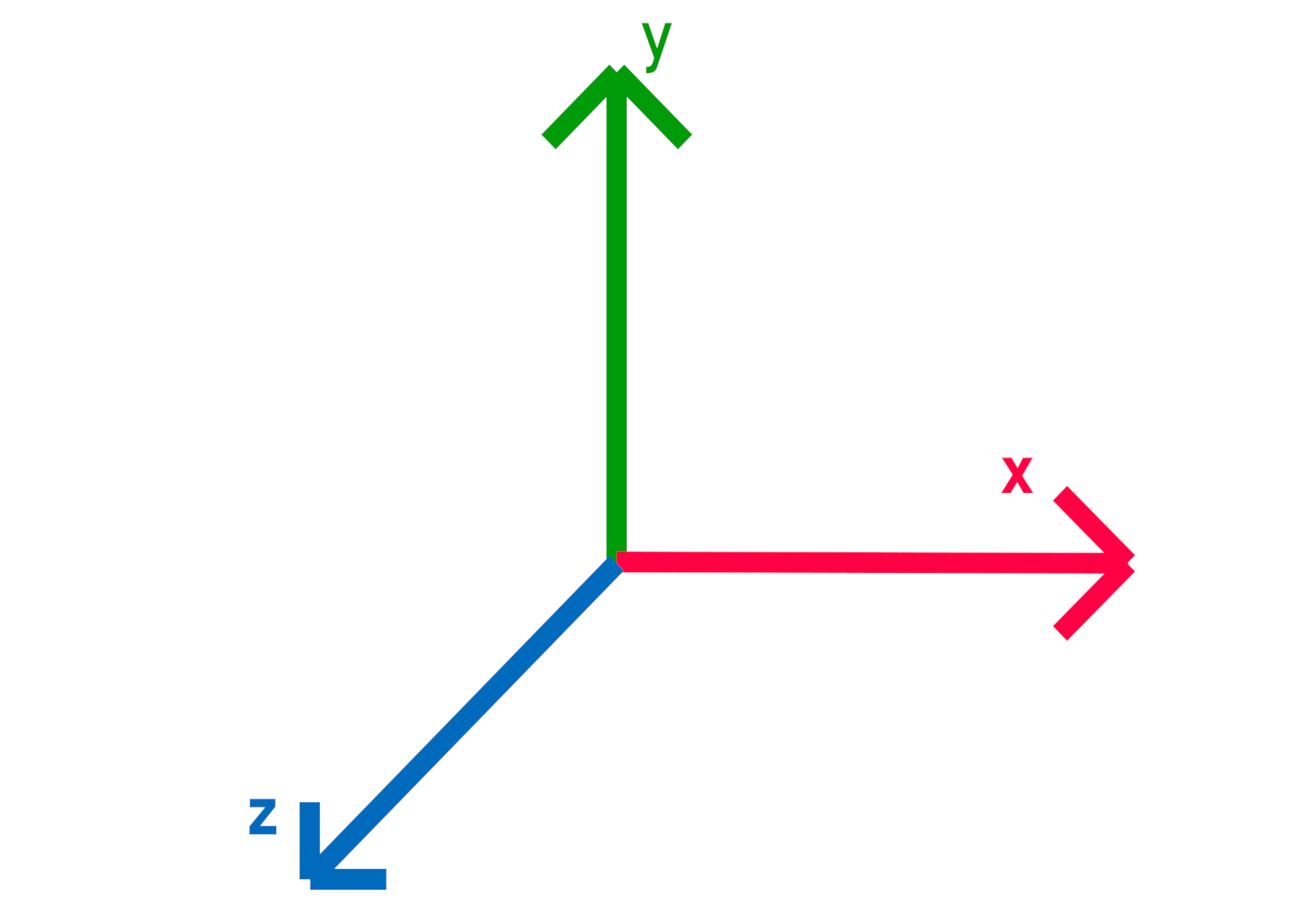
Right-handed coordinate system
We first define the forward vector which is pointing towards us. And then, we get the cross product of the scene up vector and negative forward and we get the right vector. Lastly, we get the cross product of negative forward and right and get the camera's up vector. We only need to normalize the right vector and after that, since both forward and right vectors are normalized we do not need to normalize the up vector furthermore.
Since we have the coordinate system, we can start calculating the ray direction. The rays we send to the scene look like this:
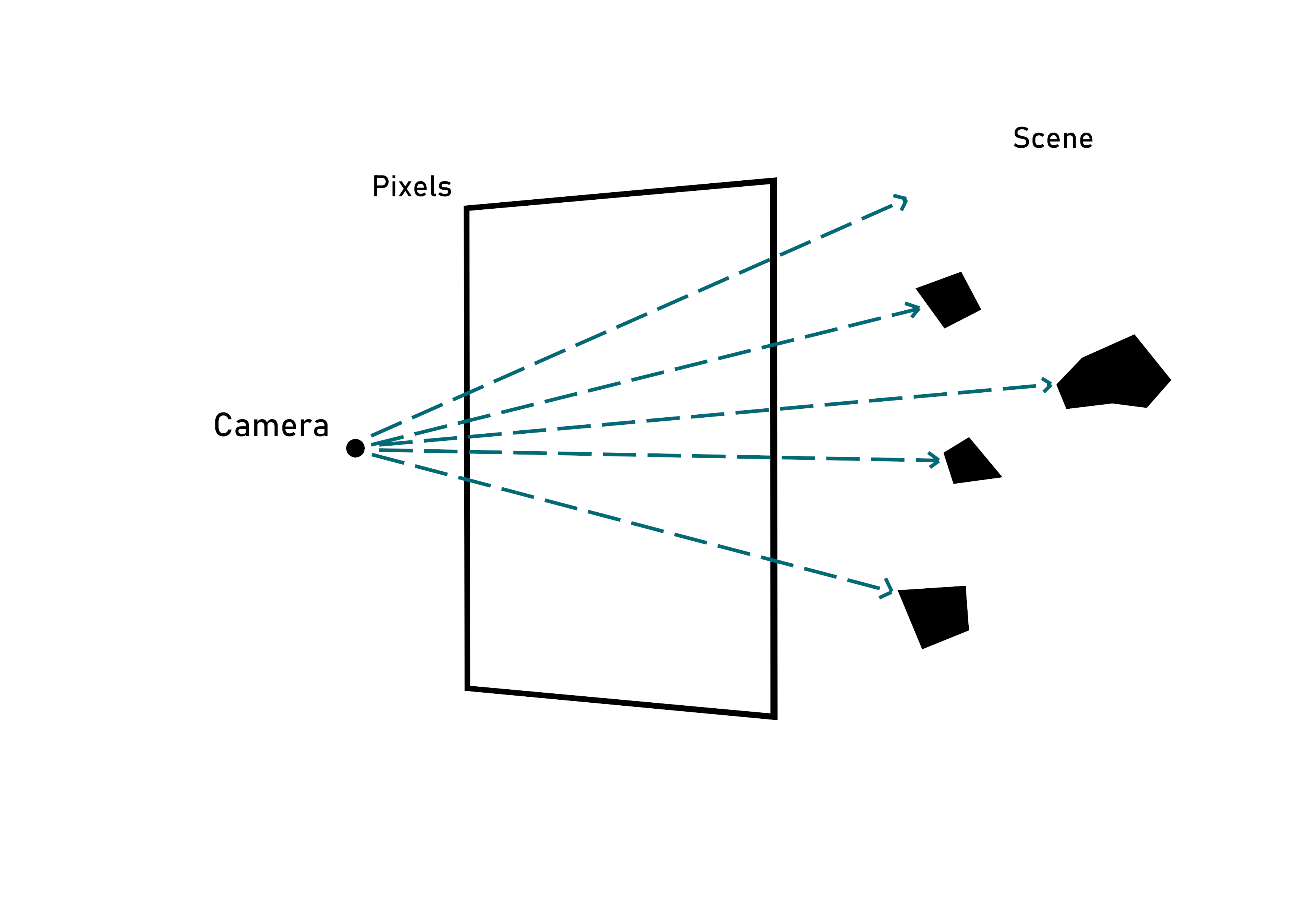
Ray Casting
For calculating the ray direction, we first need the center coordinates of the screen. We get this by moving forwards along the forward vector. We also use the zoom of the camera here and it changes the field of view of the scene. When it gets smaller, we see a lot more but perspective easily becomes so bad that objects are distorted too much. So we have to keep it in reasonable amounts.
After we find the center coordinates, we get the intersection point between the ray and the screen. Here, we use the coordinates of the pixel (uv coordinates). And finally, we get the ray direction by calculating the vector which goes from the camera's position to the intersection point and we normalize it. That's it.
Make a Camera Orbiting the Origin
For this, we will make use of rotation matrices. We can both rotate the camera position and the direction vector separately with the same rotation matrix and get the correct transformation. I also want to be able to rotate the camera using mouse coordinates. Shadertoy has uniform variables for mouse positions so we can use them. I similarly obtain mouse coordinates like I get the uv coordinates.
void mainImage( out vec4 fragColor, in vec2 fragCoord )
{
    ...

    vec2 mouse;
    if(iMouse.z != 0.0)
        mouse = (iMouse.xy / iResolution.xy*2.0 - vec2(1.0)) * vec2(iResolution.x / iResolution.y, 1.0) * 2.0;
    else
        mouse = vec2(-1.0, -0.2);
}
Now, we have to make the rotation matrices for rotating around the y-axis and x-axis. Matrices will be like the following:
We multiply these two matrices and then multiply the result with both the ray direction and the ray origin. This way, we got a camera orbiting the origin.
void mainImage( out vec4 fragColor, in vec2 fragCoord )
{
    ...

    mat3 rotationY = mat3(
        vec3(cos(mouse.x)   ,  0.0            , sin(mouse.x)),
        vec3(0.0            ,  1.0            , 0.0         ),
        vec3(-sin(mouse.x)  ,  0.0            , cos(mouse.x))

    );

    mat3 rotationX = mat3(
        vec3(1.0         ,  0.0            , 0.0),
        vec3(0.0         ,  cos(mouse.y)   , sin(mouse.y)),
        vec3(0.0         , -sin(mouse.y)   , cos(mouse.y))
    );

    mat3 rotationMatrix = rotationY * rotationX;

    vec3 rayDirection = getRayDirection(uv, cam);
    cam.Position = rotationMatrix * cam.Position;
    rayDirection = rotationMatrix * rayDirection;
}
Casting The Ray
We have the ray. So we have to use the ray marching algorithm and cast the ray. We define a function called CastRay that takes a ray and a direction and starts the ray marching algorithm. It is straightforward and it looks like the following:
float CastRay(vec3 rayOrigin, vec3 rayDirection)
{
    float t = 0.0;

    for(int i=0; i<MAX_ITERATIONS; i++) {

    	vec3 currentPosition = rayOrigin + rayDirection*t;
        float dS = GetDist(currentPosition);
        t += dS;
        if(t>MAX_DISTANCE || abs(dS)<SURFACE_DISTANCE) break;
    }

    return t;
}
In this function, there are two things to mention. First of all, there are some defines:
- MAX_ITERATIONS: Ray marching stops when after this many iterations.
- MAX_DISTANCE: If we have marched more than this distance, we break from the loop.
- SURFACE_DISTANCE: This is like an epsilon, we decide that there is a hit if the distance is less than this number. We take the distance's absolute value to ensure negative distances(ray is inside) that are very close to zero are also counted as hits.
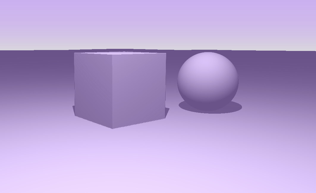
Secondly, there is a function called GetDist. This function gets the closest distance to an object in the scene from the current position. In this function, we write signed distance functions for different shapes. I will write blog posts about these shapes later. For now, this function has a plane, a sphere on the point (1.0,1.0,-3.0) and a 1x1x1 cube on the point (0.0,1.0,0.0).
float GetDist(vec3 pos)
{
    float planeDistance = pos.y;

    float sphereDistance = length(pos - vec3(1.0,1.0,-3.0)) - 1.0;
    float box = dBox(pos - vec3(0.0, 1.0, 0.0), vec3(1.0,1.0,1.0));

    float dist = min(planeDistance, sphereDistance);
    dist = min(dist, box);

    return dist;
}
So, we simply use the CastRay function in our mainImage function. CastRay function gives us a t value which is the distance to the closest object. This means that we can get the fragment position. We will use this position for calculating normal and lighting calculations:
void mainImage( out vec4 fragColor, in vec2 fragCoord )
{
    ...

    float t = CastRay(cam.Position, rayDirection);

    vec3 fragPos = cam.Position + rayDirection * t;

    vec3 outputColor = vec3(0.0);

    vec3 dif = GetLight(fragPos);
    outputColor = dif;
}
Now, we use this frag position and calculate lighting with the GetLight function. This function simulates a point light with attenuation and some ambient light simulating lights coming from the sky and bouncing from below. Get light looks like the following:
vec3 GetLight(vec3 p)
{
    vec3 lightPos       = vec3(5.0,10.0,4.0);
    vec3 lightIntensity = vec3(30.0,30.0,30.0);

    float lightDistance = length(lightPos-p);

    vec3 lightDirection = normalize(lightPos-p);
    vec3 normal         = GetNormal(p);

    // Diffuse light
    vec3 dif      = clamp(dot(normal, lightDirection), 0.0, 1.0)*lightIntensity;

    // A ray is cast to the light source for shadow calculations
    float d = CastRay(p + normal * SURFACE_DISTANCE * 2.0, lightDirection);


    float lightDif  = clamp(dot(normal, lightDirection), 0.0, 1.0);

    // If there is an object between the light and p, p is in shadow
    if(d<lightDistance)
        lightDif*=0.1;

    float attenuation = (1.0/(lightDistance*lightDistance + 0.0001));
    vec3 radiance = lightDif  * lightIntensity * attenuation;

    float bounceDif = clamp(0.5 + 0.5*dot(normal, vec3(0.0, -1.0, 0.0)), 0.0, 1.0);
    float skyDif    = clamp(0.5 + 0.5*dot(normal, vec3(0.0,  1.0, 0.0)), 0.0, 1.0);

    // We return diffuse light with attenuation
    radiance      += skyDif * vec3(0.15, 0.1, 0.25);
    radiance      += bounceDif * vec3(0.1, 0.1, 0.2);


    return radiance;
}
As seen in the code above, there is a function called GetNormal. This function is used for calculating the normal vector of the surface. It simply calls getDist function for points that are very close to the intersection point. These points are created by moving along the x, y, and z-axis just a little bit and calculating the distance again. The difference between our distance and the three distances we obtained gives us the normal direction. Code looks like the following:
vec3 GetNormal(vec3 p)
{

    float d = GetDist(p);
    vec2 e = vec2(0.01, 0.0);

    vec3 normal = d - vec3(
        GetDist(p-e.xyy),
        GetDist(p-e.yxy),
        GetDist(p-e.yyx)
    );

    return normalize(normal);
}
We also check for shadows just like in ray tracing. We cast another ray from the intersection point to the light. If we cannot reach the light, then there is a shadow on that fragment.
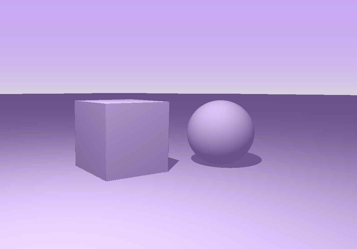
The last thing we need to do is render the sky. For that, I wanted to use the simple method I saw that is used by Inigo Quilez in his live coding session happy jumping. He simply mixes two colors for the sky, one is for normal sky color and the other one is the more greyish horizon color. He gets the mix factor from the y coordinate of the pixel and gives it the value like this:
This way, the gray color only appears near the horizon just like we want. Sky looks like the following:
Sky rendering
In the mainImage function, we do it like the following:
void mainImage( out vec4 fragColor, in vec2 fragCoord )
{
    ...

    if(t > MAX_DISTANCE)
    {
        vec3 skyColor = vec3(0.75,0.6,0.9);// - 0.7*rayDirection.y;
        vec3 skyGrey  = vec3(0.8,0.8,0.8);
        float factor  = clamp(uv.y - 0.1, 0.0, 1.0);


        outputColor = mix(skyColor, skyGrey, exp(-10.0*(factor)));
    }

}
Lastly, we have to do tone mapping because most of our pixels will have high values. I simply used uncharted2 tone mapping algorithm. In the code we write it like this:
float A = 0.15;
float B = 0.50;
float C = 0.10;
float D = 0.20;
float E = 0.02;
float F = 0.30;

vec3 W = vec3(1120.0);

vec3 uncharted2ToneMapping(vec3 x){
	return ((x*(A*x+C*B)+D*E)/(x*(A*x+B)+D*F))-E/F;
}
As I understood, it creates a curve for luminance values. We get a scale for each pixel color. We also do a gamma correction. The code looks like the following:
void mainImage( out vec4 fragColor, in vec2 fragCoord )
{
    ...

    // Gamma Correction
    vec3 whiteScale = 1.0 / uncharted2ToneMapping(W);
    vec3 mapped = outputColor * whiteScale;

    mapped = pow(mapped, vec3(.4545));
    fragColor = vec4(mapped, 1.0);

}
Conclusion
So, I have implemented a basic ray marcher that helps me learn new concepts for now. I will use this basic ray marcher when I explain things that I learned about SDF's in future blog posts.